
Unstable Transitions in HVAC Operations: Enabling the Economizer
Miles Ryan, P.E., writes a monthly column in Engineered Systems Magazine on Building Commissioning. Read January’s column below:
Periods of instability in HVAC systems often occur during necessary transitions in system operation. Examples of such instances include when a system first enables, goes from an occupied to an unoccupied mode of operation, or key components of the system (chillers, pumps, etc.) stage on or off to meet system demands.
Additional provisions in the automation of these systems are required to minimize the effects of these disturbances. Typically, not all the kinks are worked out prior to the functional performance testing directed by the commissioning provider. Our testing processes should be paying extra close attention during the transitional periods to identify any levels of unexpected instability, and we should also have a solid understanding of the tools available to the temperature controls contractor to improve performance in such instances.
This article is the fourth installment in this series. It discusses issues that often occur when an AHU’s economizer sequence is first enabled due to softening ambient conditions (i.e. outdoor air temperature, enthalpy, or both) dropping below their high limit threshold to first enable the economizer. Such transitions often result in temporary spikes in discharge air temperature (DAT) and dewpoint, which may prove to be unacceptable for certain building types.
Economizer High Limits
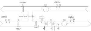
Figure 1: AHU diagram. AHU dam pers are modulated during the economizer sequence to maintain DAT at setpoint.
AHUs (see Figure 1) are typically configured to bring in a certain amount of outdoor airflow during occupied periods of the building. Another key function of an AHU is to provide DAT at a certain setpoint capable of cooling served spaces, 55°F is a conventional value used for this setpoint. During mild ambient conditions, it is advantageous for the AHU to implement an economizer sequence, which brings in more outdoor airflow than the minimum ventilation requirements, in an effort to eliminate, or at least reduce the amount of mechanical cooling needed in order to land the DAT on setpoint.
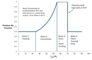
Figure 2: Stages of DAT temperature control. A constant volume AHU was used for illustrative purposes. 55°F DAT setpoint used in figure, though a lower setpoint is often used for AHUs serving ORs. Assume fan heat (which would raise temperature of airstream) is negligible for illustrative purposes.
If ambient conditions are below the DAT setpoint (state 2 in Figure 2), mechanical cooling may be eliminated altogether. But even if the outdoor air temperature is above DAT setpoint (state 3 in Figure 2), it is still advantageous to bring in 100% outdoor air while running the mechanical cooling as well. For example, if the outdoor air temperature is 60°F and the return air temperature is 72°F, then it is less energy intensive to cool outdoor air (60°F) down to 55°F (DAT setpoint), rather than cooling down a 40/60 mixture of outdoor and return air (67.2°F). The overall intent is for the economizer (first stage of cooling) to be maxed out prior to engaging mechanical cooling (second stage of cooling), and there are numerous methods in which temperature controls contractors program the system to achieve this.
There comes a time when it is no longer advantageous to bring in higher quantities of outdoor air, as it may have a higher energy content (i.e. enthalpy) than the return air. In such instances, it is beneficial to resort back to bringing in just the minimum outdoor airflow. A common high limit used to predict when this scenario is reached, is that of fixed dry bulb, which compares outdoor air temperature to a high limit (e.g. 70°F in ASHRAE climate zone 6a1). Similarly, when outdoor air temperature drops below that high limit, the economizer sequence transitions from disabled to enabled. It is this transition when the economizer is first enabled which often creates instability that is overlooked.
The Issue
Imagine it is 71°F outside with return air temperature at 72°F. The economizer is disabled (state 4 of Figure 2) and only mechanical cooling (i.e. the cooling coil) is available to keep the DAT at setpoint of 55°F. If the outdoor air temperature drops below the economizer high limit (let’s assume 70°F) then the economizer will enable. The economizer (which positions AHU dampers to bring in higher quantities of outdoor airflow above minimum requirements) then becomes the first stage of cooling. To maximize energy savings, the economizer control loop must be maxed out (100% outdoor air) prior to the cooling valve opening.
So, when the unit first transitions into economizer mode, the cooling valve slams closed, and we have to wait for the economizer control loop to ramp up to 100% prior to allowing that cooling valve to open again. While the economizer control loop slowly ramps, it will slowly drop the mixed air temperature from 71.2 °F at minimum outdoor airflow to 70°F at 100% outdoor airflow. During that economizer ramp up period, the cooling coil is quickly warmed up as there is no chilled water flowing through it, and the DAT quickly starts to track on the mixed air temperature. Even with the economizer fully open, the DAT will still be 15°F above setpoint. Only then will the cooling valve be allowed to enable to give DAT the chance to again track on setpoint.
This transition period may last up to 20 minutes or more. Economizer control loops are often configured to be very slow responding control loops, which is fine once the system stabilizes, but that really creates chaos during the transition into economizer mode. During that long delay, DAT may reach 70°F, well above setpoint. This may create temperature control issues out in the building. A greater concern, however, is that no latent cooling is possible during this transition period. The resultant dewpoint of discharge air may ramp up if there is high humidity in the outdoor air.
This period of lost control of the DAT when first enabling the economizer is often not noticed when the AHU is serving an office space, but it can create disorder when the AHU is serving critical spaces with high air change per hour requirements, as well as tight temperature and humidity tolerances.
One example is an AHU serving a suite of operating rooms (ORs). Those AHUs often operate at an even lower DAT setpoint (e.g. 48-50°F), thus the resultant error between DAT and DAT setpoint is even greater during the transition period. That spike in AHU DAT is often quickly compensated for by the reheat coil in the duct leading to the operating room quickly backing off, and temperature fluctuations within the OR may be negligible. It is the relative humidity that has the tendency to spike. If the dewpoint of air entering the space goes from 46°F with the economizer disabled to 60°F or higher after the economizer is enabled but the cooling valve (second stage of cooling) has yet to begin reopening, then the relative humidity in the OR operating at a space temperate of 68°F may rise from 46% to 76% or higher. Such humidity is tightly tracked and often alarmed if it rises above 60%. This is a compliance issue and a hot button-item for healthcare facility staff, but the root cause of the spike in humidity may not be intuitive to them.
I have seen this exact situation occur in two separate hospitals, but it can be overcome.
The Fix
There needs to be a more gradual handoff between the cooling valve operating alone (state 4 of Figure 2) and operating with the economizer (state 3 of Figure 2). Various programing efforts can be used to improve this. Here are a couple:
- Have the economizer control loop modulate the AHU dampers to keep mixed air temperature at a fixed setpoint (often a fixed offset below AHU DAT setpoint). This approach was common for years. More design engineers are going away from it as it has a tendency to prematurely enable the cooling valve in Stage 3 or simultaneously heat and economize, but this old school approach does eliminate the concerns of instability laid out in this article.
- Staggering of DAT setpoints for which the cooling valve and economizer control to. E.g. the cooling valve may control to 50°F DAT setpoint while the economizer controls to 49°
- Configure the economizer control loop to start at an output of 100% when it first enables. That will force the dampers into a 100% outdoor airflow configuration much quicker than waiting for the economizer control loop to ramp from 0-100% over an extended period of time. Since the first stage of cooling (economizer) will be maxed out immediately upon the economizer enabling, that will allow the cooling valve (second stage) to be available quicker. A further improvement to this approach would be to implement a delay-on-break on the cooling valve when first entering economizer mode. This may involve putting a rate limiter on the valve’s closing rate so that it cannot slam closed even if DAT is falling below setpoint.
Conclusion
There are plenty of other options for achieving a stable transition into economizer mode. The intent of this article is not to list them all but rather make readers aware of this instability. It is often overlooked, which may not have many consequences for a lot of the buildings out there. I never caught onto this until I started working in healthcare and was asked to troubleshoot unexplained spikes in ORs’ relatively humidity. Commissioning providers should pay extra close attention while testing this specific transition, especially for AHUs serving critical applications. And it is best for the commissioning provider to work with the team to avoid such a situation well prior to the functional testing stage of a project.
References:
1 ASHRAE Guideline 36-2021, High-Performance Sequences of Operation for HVAC Systems.