
The Case for Softening DHW
Miles Ryan, P.E., writes a monthly column in Engineered Systems Magazine on Building Commissioning. Read February’s column below:
Recommendations from commissioning providers to owners, designers, contractors, etc., often are validated by field experience. For credibility purposes, having lived those experiences yourself is ideal. However, much can be learned from others’ hard taught lessons as well. The project detailed below provided me with all the examples I need to be convinced that soft water in domestic hot water (DHW) systems is a necessity and a recommendation for softening such water to project teams has become a standard of mine when the potable water supply is hard. This article intends to convince the readers of this as well.
Project Background
Back in 2020, I got brought into work at a high-rise condominium that was plagued by a ton of different issues surrounding its DHW system. The next 18 months involved numerous investigations, repairs, and modifications to get the system operating correctly. One underlying issue that wreaked havoc on the system was excessive amounts of scale that were accumulating in various locations of the DHW system. The system was not, and still is not, softened. This is primarily due to logistics. The homeowner’s association and property management company did not want to entertain lugging endless amounts of salt up several stories of stairs to get the mechanical penthouse where the primary equipment of the DHW system was located.
This DHW system has to be one of the more complicated systems out there. Figure 1 is a simplified schematic that contains the system components talked about in this article. The water-tube boilers are configured lead/standby (i.e. full redundancy). They are referred to as boilers in lieu of water heaters due to their large output capacity. They have single stage burners (on/off control) and cycle to maintain water in the storage tank around 145°F. The lead boiler’s respective boiler pump operates continuously. High temperature water is pulled from the storage tank and sent to two electronic mixing valves (MV-1 and MV-2), which knock the water temperature down to 128°F before it is sent to the fixtures throughout the building. A separate mixing valve (MV-3) produces 136°F water which is sent to the primary side of water-to-water heat exchangers (not shown) out in the building which keeps recirculated DHW at the floors below at suitable temperatures to allow for hot water to be available at fixtures in a short period of time. Pump P-3 brings water back from the primary side of those recirculation heat exchangers. There are no control valves on those heat exchangers, so P-3’s speed is modulated to maintain a constant flow rate as measured at the flow meter shown in Figure 1.
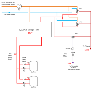
Figure 1: Simplified schematic of the DHW system.
Defining Scale
Water hardness is essentially a measure of the amount of dissolved calcium and magnesium in the water. Water softeners work to remove such minerals from the water supply. When water softeners are not present and hard water is utilized, those minerals will precipitate from the water and produce calcium carbonate scale, also known as limescale.
When hard water is evaporated, the calcium and magnesium salts are left behind. Those scale deposits are commonly visible at the discharge of various plumbing fixtures. What is typically not visible is scale buildup within the components of a domestic water system. Elevated water temperatures of DHW systems result in lower solubility of calcium and magnesium in water, which means those minerals are more likely to precipitate out and produce scale (reference Figure 2). This creates operational issues for the equipment within the system. As the system under discussion in this article was not softened, we had more than our fair share of fights with scale within the major components of the DHW system.
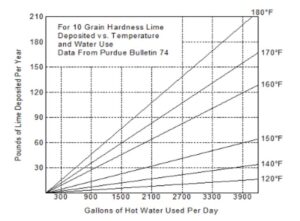
Figure 2: Scale accumulation as a function of operating temperature.
Boiler kettling
One of the issues pointed out by the building engineer early on was a very loud popping noise coming out of one of the boilers. Initially, we just ran the other boiler while our investigation into the rest of the system continued. However, then that boiler also started popping which forced us to focus on the boilers. The popping was terrifying to listen to, and all the pipes would shake very aggressively when it occurred. It was quickly diagnosed as boiler kettling, an instance where localized pockets of water boiled into gaseous phase, only to collapse further downstream. Such collapsing is like mini implosions that send shock waves throughout the system which manifest in the shaking pipes and loud popping noises. This is basically the effect seen in cavitation, just that localized higher temperatures within the boiler’s heat exchanger induce the initial phase change, not localized drops in static pressure like that seen in cavitation at pumps.
After consulting with the boiler manufacturer, we initially believed the reason for the kettling was improper pump operation and pump sizing. The automation system was initially running both boiler pumps continuously, which resulted in less flow through a single boiler than if just one pump was running due to the fact the pumps shared some common piping. But disabling one pump alone did not get us away from the popping. Reverse engineering of the piping system and comparing the developed system curve to the pump curve of the existing boiler pumps, we found ~45 GPM was going through the boiler. This was confirmed by comparing it to the ~40°F temperature rise that was being observed across the boiler.
The remedy was to upsize the boiler pumps, to increase flow and decrease temperature rise across the boiler (see Figure 3). This would result in a lower temperature rise realized within the water as it traveled through the boiler’s heat exchanger. While we waited for the new pumps to arrive, the popping was getting so severe that the building engineer was sleeping at the building in case a pipe broke. We assumed we had some scale build up within the circuits of the boilers’ heat exchangers, so during the pump replacements, we flushed the heat exchangers with the boiler manufacturer’s recommended deliming solvent.
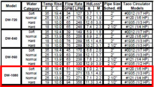
Figure 3: Heat exchanger performance chart (Reference: A.O. Smith DuraMax IOM Manual).
The pump replacement and deliming solvent did NOT do the trick! We were still kettling once we reenabled the boilers. We figured there must be localized blockages within one or more of the circuits of the two boilers’ heat exchangers. We opened the heat exchangers and found the culprits, see Photo 1.
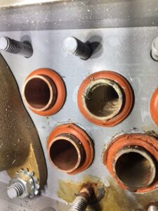
Photo 1: Scale accumulation within water tube of Boiler 2.
Excessive scale had accumulated in at least one circuit on each of the boilers’ heat exchangers and was severely restricting flow, resulting in localized boiling, and subsequent collapsing of vapor pockets back to liquid form. After abrasively cleaning all circuits, all the kettling went away on both boilers!
It dawned on us that once the scale starts occurring, it will only get worse. Scale will restrict water flow, which will result in higher localized temperatures, which reduces the solubility of calcium and magnesium in water, which results in more scale formation. It is a downward spiral, one that needs to be identified early on going forward.
Check Valve Performance
Dealing with the boiler kettling led us to two conclusions:
- We need to operate just one boiler and boiler pump at a time to maximize flow, minimize temperature rise across the boiler, and in turn reduce scale buildup.
- We need to monitor the temperature rise across the boiler via the available building automation system (BAS) sensors to identify when scale accumulation starts restricting flow an appreciable amount.
After the upsizing of the boiler pumps and cleaning of the boilers’ heat exchangers, we initially witnessed about a 20°F temperature rise across an operational boiler. We arbitrarily decided we would flush the heat exchanger with the manufacturer’s recommended deliming solvent when the temperature rise started to exceed 25°F. Unfortunately, that scenario occurred within weeks. We applied another deliming solvent treatment, but still saw the 25°F temperature rise on the BAS. We opened up the heat exchanger again (a labor-intensive process), but this time found clean circuits. Running the boiler again, we realized readings on the inlet and discharge thermometers of the standby boiler to be closely matching the discharge temperature of the operating boiler. The check valve seemed suspect, and when pulled apart, we found slugs of scale were preventing them from fully seating (see Photo 2). This allowed hot water from the discharge of the operating boiler to short circuit through the standby boiler and back to the inlet of the operating boiler. This raised inlet temperature of operating boiler to about 5°F above that what the BAS sensor was reporting as inlet temperature, hence the reason we thought we were seeing an increase in temperature differential across the operating boiler.
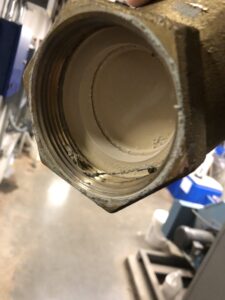
Photo 2: Scale accumulation on check valve downstream of boiler.
Mixing Valve Reliability
Mixing Valves MV-1 and MV-2 were electronic mixing valves installed just prior to the start of our comprehensive investigation. They contained a digital display of their output temperature to be viewed in real-time. Observation of this temperature quickly identified the valves were hunting excessively around the setpoint of 128°F. There were several instances when the temperature rose far enough above setpoint that an internal high limit safety triggered which positions the valve to the cold inlet port. This flooded the DHW distribution system with cold water. Such hunting and safety lockouts were exacerbated during periods of low flow (i.e. middle of the night). And since the electronic mixing valves had to be power cycled to be reset, this resulted in a slow and inconvenient response by the building engineer (who was sleeping at his house 20 minutes away during such periods).
The contractor who installed these electronic mixing valves was called back on several instances to investigate. In all instances, they found excessive scale both within the valves themselves, but also in the strainers just upstream of the hot side inlet ports.
The work done to address the boiler kettling, which is detailed earlier in this article, drastically improved the controllability of these mixing valves as well.
Building Drain Downs
This article does not scratch the surface on the amount of work that had to be performed on this DHW system. A lot of the work incurred full or partial drain downs of the system. When the system was drained, and subsequently refilled, it jostled up a lot of scale which quickly made its way to fixtures, which reduced or completely prohibited flow at the fixture. This issue become so predictable that at one stage of the project, when the entire building had to be drained, three separate plumbing contractors were asked to remain on site for several hours to respond to the large number of clogged fixture complaints from residents.
Recirculation Heat Exchangers
As referenced earlier, there were several heat exchangers used out in the DHW distribution system which kept recirculated water warm. The 136°F DHW was used on the primary side to keep recirculated water available to the fixtures at reasonable temperatures. From the onset of the project, the performance of these heat exchangers was suspect. Throughout the project, each of the 4 heat exchangers were either replaced or removed, cleaned and put back in service. Scale accumulation within the heat exchanger (see Photo 3) was one of the primary reasons for inadequate performance, that along with undersized recirculation pumps, clogged balancing valves (due to scale) and lack of insulation.
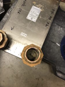
Photo 3: Scale accumulation within heat exchanger serving the DHW recirculation system.
Pump P-3 Operation
After all major work that came from our investigation was completed, I would come back to site every other month to review operation and make minor tweaks to various balancing valves and automation parameters. The flow reading of the 136°F supply water, which P-3 controls to, started to trend downwards even with the pump’s speed maxed out. We blew down the stainer on the inlet of the flow meter, but it didn’t make a difference. We backflushed all the recirculation heat exchangers further downstream, but it didn’t seem slow down the decline in measured flow. We even had a balancer come out and confirm accurate flow readings were provided by the flow meter. The reduction in flow dropped off exponentially, which eventually resulted in complaints from residents as they were no longer getting DHW at their fixtures in a reasonable timeframe. We finally found the culprit after disassembling the strainer on the inlet of the flow meter (see Photo 4). It was…. scale!
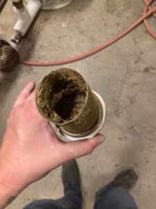
Photo 4: Scale accumulation in strainer upstream of flow meter.
Conclusion
Not every DHW has to be softened. Logistics, costs, incoming water hardness, maintenance resources and operating temperatures all play a part in that decision process. However, being aware of the issues that can come from not softening DHW system and added level of maintenance needed for such systems is essential knowledge for commissioning providers who are working with such new and existing systems. For this particular system, numerous additional preventive maintenance tasks were added to the services contractor’s scope based on lessons learned through the process.
Acknowledgements
Special thanks to Ryan Tatton of Apollo Water Services in Chanhassen, MN for his expertise during this project and for the proof-reading of this article.