
Improving HVAC Operations – Part V: Managing Swing Season Heating Requirements
Abstract:
Maintaining a solid understanding of how common HVAC systems are controlled is essential to effectively troubleshooting them. It is also necessary for optimizing the energy performance of such systems. Improving the knowledge base of HVAC control sequences throughout the Department of Defense, for these purposes, was the driving force behind the resurrection of the Air Force Institute of Technology’s course entitled WENG 563 HVAC Control Systems. This 5-part series is written to support that course. These articles seek to explain common HVAC control sequences, where such sequences are effective, and the performance implications that arise when they are applied inappropriately.
Please enjoy Part V of this series below written by Questions & Solutions Engineering’s own Miles Ryan, PE, CEM.
Part V: Managing Swing Season Heating Requirements
A previous article in this series highlighted how a simple adjustment to an HVAC control sequence can greatly benefit occupants on warmer days in the spring or fall when their building’s chiller has been disabled (Ryan and Dill, 2019). In many climates, occupants can be subjected to colder-than-desired temperatures during these swing seasons as well. A common reason being the hot water system which heats the building may be disabled. This could be due to policy (e.g. a local ban on cooling season reheat to save energy) or it could be a necessity (e.g. spring is a good time to start repairing all those hot water systems that were limped along through the winter). There are control sequences which when inappropriately applied can unnecessarily exacerbate the chilling of our occupants. This article describes such a sequence pitfall.
The Variable Air Volume Box
The most common HVAC system we see in our commercial buildings today is a multi-zone, single-duct variable air volume (VAV) system. Essentially, the temperature of the air being sent out to the various spaces served is maintained at some constant temperature back at the air handling unit (AHU). That temperature is typically on the order of 55-65°F. If a space is demanding additional cooling, the VAV box in the ductwork leading to that space will open its damper to allow for larger quantities of cool air to pour into the space (see Figure 1). As cooling demand diminishes, the damper will restrict airflow into the space. The flow rate of air cannot be restricted too much though. These boxes will not let the airflow drop below a predetermined minimum flow rate (as measured by its internal flow sensor) to ensure adequate ventilation is provided to the occupants. If the space temperature continues to drop when the box is at minimum flow, we might need to warm up that air a bit before we send it into the space. We do that with a reheat coil, also located in the VAV box.
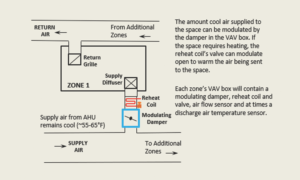
Figure 1: A typical zone served by a VAV box with reheat.
Conventional VAV Box Control Logic (Constant Heating Airflow)
The conventional logic for how a VAV box with a hot water reheat coil operates can be seen in Figure 2. During heating, the airflow rate into the space remains constant at the minimum rate, but the air stream’s temperature is increased as needed by the reheat coil. This conventional logic is by far the most prevalent sequence seen in the Air Force, but other logics do exist.
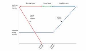
Figure 2: Conventional VAV Box Control Logic.
Unconventional VAV Box Control Logic (Varying Heating Airflow)
There are many variations of control logic which varies the airflow rate within the heating loop, a simple version of it is shown in Figure 3. As the VAV transitions into heating, the reheat valve begins to open while the airflow rate is simultaneously increased. The airflow does not remain at its minimum value during heating as it does in the conventional logic. There are numerous advantages to varying the heating airflow as will be outlined below. However, if the hot water system were disabled, the heating loop will become unstable. Imagine your space started calling for heat, but the hot water system was disabled. Increased calls for heating will result in increased amounts of cold air sent to the space. This is a very unstable scenario which will result in the VAV box stuck at maximum heating airflow and the space temperature far colder than it would be if the VAV box had just remained at minimum airflow. This could be avoided with appropriate interlocks put in place to disable the VAV box’s heating loop when the hot water system is disabled. However, this is not always the case.
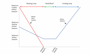
Figure 3: Unconventional VAV Box Control Logic can become unstable in the heating loop if the hot water system is disabled.
Case Studies – Comfort Issues with Unconventional VAV Box Control Logic
A City Hall in Southeastern Minnesota was recommissioned in the summer of 2018. One day during the study, one space was experiencing temperatures far below even its heating setpoint, and it was 88°F outside! Though this building often operated both the chilled water and hot water systems simultaneously, the hot water system was programmed to be disabled when the outdoor air temperature rose above 80°F. No interlock was in place to disable the heating loop for the VAV box when the hot water system was disabled. This space received higher amounts of cold air upon a request for heating.
A similar situation was realized that same summer at an elementary school just outside of Minneapolis. In this building, the heating loop was disabled anytime the outdoor air temperature was above 57°F. This initially made sense, since the boiler plant is only enabled at outdoor air temperatures of 57°F and below. However, the boiler plant was seasonally disabled at the local disconnect switch, and the VAV boxes did not know it. A cool August morning at 52°F outside resulted in many spaces being pushed several degrees below their heating setpoint.
In both these buildings, the majority of the VAV boxes had heating maximum airflow rates which matched the cooling airflow rates. This violates ASHRAE Standard 90.1, and it further intensified the overcooling of the spaces.
Case Study – Energy Waste
Both the case studies just outlined will result in higher fan energy waste, since the systems were pushing more airflow than they should when the hot water system was disabled. But the elementary school experienced excessive energy consumption even when the boilers were enabled due to additional shortcomings in the programming. The airflow rate was intended to increase in tandem with the opening of the reheat valve as shown in Figure 3. Instead, they were operating off separate control loops. As the airflow’s control loop was far more sensitive than the reheat valve’s, the slightest call for heating resulted in the airflow rate being reset to its heating maximum. The reheat valve then slowly increased until the space settled at its heating setpoint. The space eventually maintained its temperature setpoint, but at an airflow rate and reheat valve position far greater than required. Trend analysis proved this was indeed the case for most of the boxes in the building. Conservative estimates show savings of over $2,500 annually could be realized through reprogramming this sequence.
Dual Maximum
ASHRAE published Guideline 36: High-Performance Sequences of Operation for HVAC Systems in 2018. It describes the best-in-class VAV box control logic, which includes varying heating airflows. This variation, dubbeddual maximum, is detailed in Figure 4 (Taylor et al, 2012). In this sequence’s heating loop, the hot water valve controls to a discharge air temperature (DAT) setpoint. This first stage of heating resets this setpoint upward upon a space’s call for heating. This setpoint rises to a maximum value (typically 85-90°F) before airflow is ever increases. The second stage of heating increases the airflow while controlling the reheat valve to maintain this maximum DAT setpoint. Guideline 36 contains a provision which prevents the airflow from being increased unless the DAT measures at least 5°F above the space temperature.
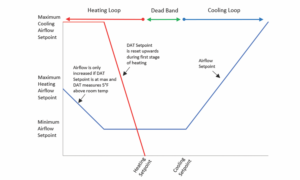
Figure 4: Variation of Unconventional VAV Box Control Logic dubbed dual maximum. It has a provision to prevent the airflow setpoint within the heating loop from increasing when the hot water system is disabled. A discharge air temperature sensor is needed to implement this logic.
This logic has numerous other benefits over conventional logic. It can save fan energy, reheat energy and cooling energy. It can prevent short circuiting of excessively warm supply air into the return grille. It can even self-balance the hot water system. These benefits may not be intuitive, but explanations are beyond the scope of this article. “Dual Maximum VAV Box Control Logic” provides further explanation. Even when the hot water system is disabled, dualmaximum typically maintains a lower minimum airflow setpoint than conventional logic, which further reduces the extent to which spaces are overcooled.
When appropriately applied, dual maximum is optimal for both comfort and energy performance. It should be no surprise that in many applications, it is required by ASHRAE Standard 90.1.
Conclusion
Disabling our heating hot water systems during warmer periods of the year is often done either to save energy or by necessity. This may result in your work spaces becoming uncomfortably cool. Inappropriate application of VAV box control logic which varies the heating airflow can not only make the spaces even colder, but will unnecessarily drive up fan energy consumption as well. For existing systems with such control logic, we must ensure the heating loop in this logic is interlocked to the hot water system to prevent this. For new systems, the dual maximum logic laid out by Guideline 36 has this interlock in place and will ensure optimized comfort and energy performance.
References:
- ASHRAE/ANSI/IES Standard 90.1. (2016). Energy Standard for Buildings Except Low-Rise Residential Buildings. American Society of Heating, Refrigerating and Air Conditioning Engineers.
- ASHRAE Guideline 36. (2018). High Performance Sequences of Operation for HVAC Systems. American Society of Heating, Refrigerating and Air Conditioning Engineers.
- Ryan, M., & Dill, J. (2021). Improving HVAC Operations Part I: Managing Swing Season Cooling Requirements.
- Taylor, S., Stein, J., Paliaga, G., Cheng, H. (2012). Dual Maximum VAV Box Control Logic. ASHRAE Journal,54(12).
Ryan is a commissioning engineer at Questions & Solutions Engineering in Chaska, MN. As an Air Force Reservist, he serves as a mechanical systems instructor at the Air Force Institute of Technology (AFIT). He is one of the developers of the HVAC Control Systems course taught at AFIT.