
Addressing PRVs in Domestic Hot Water Recirculating Systems
Synopsis
There are numerous parallels and striking differences between domestic hot water recirculating systems, and the hydronic systems used to heat and cool facilities. This paper will explore those parallels and differences to highlight the common pitfalls seen in the design and operation of domestic hot water recirculating systems which include the presence of a pressure reducing valve. Maintaining pressure requirements for adequate fixture performance at widely varying elevations often results in the introduction of such pressure reducing valves. Such valves are often accounted for incorrectly in the recirculating pump selection process, which can result in the deadheading of the pumps and ultimately a lack of hot water on-demand at most fixtures. Attention must also be paid to the location of the recirculating pump in the system to avoid sections of piping from experiencing negative gauge pressures.
About the Authors
Miles Ryan is a commissioning engineer at Questions & Solutions Engineering in Chaska, MN. He has ten years’ experience in the industry, getting his start as a Civil Engineering officer in the Air Force. He served in various roles overseeing the design, construction and operation of facility mechanical systems at Grand Forks AFB, ND. In 2015, he became a mechanical systems instructor at the Air Force Institute of Technology (AFIT). Since leaving active duty in 2018, he has remained on faculty at AFIT to continue teaching courses in HVAC control systems as well as HVAC design and analysis.
Introduction
Having domestic hot water (DHW) available at fixtures throughout a building in a reasonable timeframe can be difficult without the use of a recirculating pump. These recirculating pumps ensure that adequately warm water temperature is maintained throughout the DHW distribution syst codes require such recirculating pumps for buildings above three stories in height1, or for any building whose most remote fixture exceeds a defined maximum distance from the hot water source1,2.
These fixtures are intended to operate within a specified range of static pressures, typically 30-80 psig. Fixtures at lower elevations in a building will maintain higher static pressure than those at higher elevations. For high-rise buildings, the difference in pressure between lower level fixtures and upper level fixtures may become unacceptable. For instance, DHW at 40 psig on the eleventh floor of a building may have 90 psig or more pressure on the first floor, unless a pressure reducing valve (PRV) is introduced into the system. PRVs can be used to reduce the static pressure in the DHW distribution system for lower floors3. This helps the user of the fixture in controlling the temperature and flow rate of water exiting the fixture. PRVs are typically needed for the domestic cold water (DCW) system as well, and the PRVs’ pressure settings must be coordinated for the DCW and DHW to mitigate crossover, which is the unintended flow from DHW into the DCW piping at the fixture mixing valve, or vis versa4.
Though the introduction of PRVs in the a DHW recirculating system is often necessary, they are frequently accounted for incorrectly. This can result in insufficient operation of the DHW recirculating system. This paper explores several common examples of how these PRVs are accounted for incorrectly.
Hydronic Systems
Hydronic systems used to heat and cool facilities are typically classified into one of two categories: closed hydronic systems and open hydronic systems. During the design of such systems, it is critical the design engineer understand which type of hydronic system he or she is working with, as it will play a pivotal role in the pump selection process as well as pump location. These concepts of closed and open hydronic loops also apply to DHW recirculating systems. However, this is often not realized, and inappropriate pump selection and location occurs.
Closed Hydronic Systems
Closed hydronic systems, often referred to as closed water systems or just closed systems, are defined as a system with “no more than one point of interface with a compressible gas or surface, and that will not create system flow by changes in elevation5.” A simple example of a closed hydronic system is shown in Figure A below. This is a single load heating hot water system with no modulating control valves.
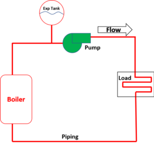
Figure A: Closed hydronic system
As fluid flow is increased through the piping system, the pressure drop in the loop increases exponentially. Pressure drop is proportional to the flow rate squared. This is commonly demonstrated by a system curve, as shown in Figure B. The total drop in pressure throughout the piping system would be the differential pressure the pump would need to provide to the system. Pumps operate on their pump curve, also shown in Figure B. Thus, it is the intersection of the system curve(which is dependent on the geometry of the piping system) and pump curve (which is a function of the pump being installed) which dictates where the system will operate. The intersection of the two curves is commonly referred to as the operating point.
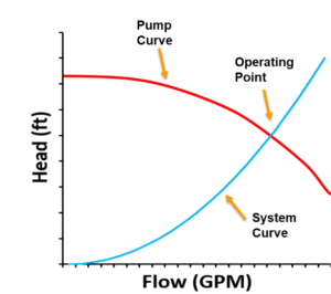
Figure B: System and pump curves in closed hydronic systems
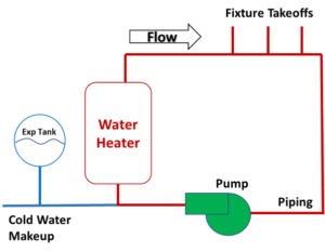
Figure C: Simple DHW recirculating system
Many DHW recirculating systems that do not maintain a PRV are example of a closed hydronic system (Figure C). Limitations of available pumps rarely results in the pump curve intersecting the system curve exactly at design flow. A slightly undersized pump will push a little less flow than designed for, and a slightly oversized pump will push a little more (Figure D). There are various methods, often seen in hydronic systems used for heating and cooling, to align the operating point with the scheduled design flow for the system when the pump is slightly oversized.
- Throttling of flow with system valves can steepen the system curve until the operating point aligns with design flow.
- If the pump has a drive, the pump curve can be manipulated by slowing down the pump until the operating point aligns with design flow.
- Pump impellers can be trimmed to manipulate the pump curve so it intersects the system curve at design flow as well.
These methods are often not employed in DHW recirculating systems since they are costly, and often unnecessary as the nature of a DHW system can often allow for slight deviations from design flow with minimal drawbacks. The use of electronically commutated motors (ECM) on recirculating pumps is becoming more common, which allows for slowing down the pump until the operating point aligns with design flow. However, the majority of DHW recirculating systems this author has encountered do not have such pumps.
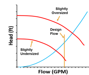
Figure D: Finding the correct pump
Open Hydronic Systems
Open hydronic systems, often referred to as open water systems or just open systems, are defined as a system with more than one point of interface with a compressible gas or surface5. The most common example of such an open hydronic system in an HVAC application would be that of a condenser water system as shown in Figure E. The two interfaces with a compressible gas would be the locations at the top and bottom of the tower.
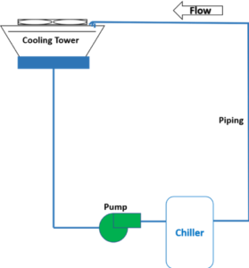
Figure E: Open hydronic system
The pressure the pump must put into the water in this open hydronic system has two components to it. Essentially the pump will need to suck water from the basin of the tower and push it to the top of the tower. Thus, it will first have to overcome the pressure associated with a column of water equal to the height of the tower. Additional pressure will need to be supplied to overcome pressure losses in the piping system. As flow is increased through the piping system, this second component of pressure drop increases exponentially, just like in a closed hydronic system. In this open hydronic system, the pump first must overcome the fixed pressure drop associated with the height of the tower before any water starts to flow. Thus, the system curve does not interest at the origin of the plot shown in Figure F below.
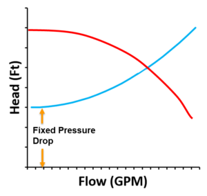
Figure F: System and pump curves in open hydronic systems
The pump selection process would be the same here, a pump must be chosen whose pump curve intersects the system curve at design flow or slightly more.
It is easy to associate open hydronic systems with systems that transport water through an elevation change as happens in condenser water systems, irrigation systems, sump pump applications, etc. It is not as intuitive to realize that DHW recirculating systems which contain a PRV have the same characteristics associated with them.
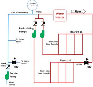
Figure G: High-Rise DHW Recirculating System
Figure G above depicts a DHW recirculating system for a high-rise application. The booster pump pushes water from the water service entrance up to the top floor of a building. The booster pump is controlled to maintain pressure at setpoint on the top floor (40 psig in this example). As water flows through the water heater and down to the floors below, static pressure builds. Thus, the DHW piping serving the Floors 1-8 needs to be downstream of a PRV to ensure appropriate pressures are maintained at fixtures on those floors.
The pressure the recirculating pump serving Floors 1-8 must put into the water system has two components to it. First, it will have to overcome a fixed pressure drop that the presence the PRV creates. The PRV controls for a discharge pressure of 40 psig, but the inlet pressure at the PRV fluctuates depending on system flow through the piping between the top floor and the PRV. Higher system flow results in higher pressure drop in the piping leading to the PRV and a lower required pressure drop across the PRV, but the sum of the two will remain constant. The easiest scenario to analyze would be that of no flow in the system, thus the static pressure on the upstream side of PRV may be 80 psig to account for the drop in elevation. The fixed pressure drop associated with the presence of the PRV would then just be the pressure drop across the PRV, which is 40 psid (92 feet of head) in such a scenario. The second component of the pressure the pump would need to overcome would be the pressure drop associated with the piping losses from the discharge of the PRV up to the reference pressure of 40 psig in the top floor. That component of pressure drop increases exponentially with flow rate.
This all has a striking resemblance to the condenser water system example. As with the condenser water system, increases in flow through the DHW recirculating system exponentially increases this second component of pressure drop, but the pump first must overcome the fixed pressure drop associated with the PRV and its upstream piping. Thus, the system curve does not interest at the 0,0 point on the plot shown in Figure F.
Therein lies a recipe for disaster. If it is not realized the fixed pressure drop associated with introducing a PRV creates a scenario with all the characteristics of an open hydronic system, a pump may be scheduled, selected and installed that is inappropriately sized. An undersized pump in a closed hydronic system will still result in flow, but just less than design (Figure D). Slightly less than design DHW flow may not even be realized. However, an undersized pump in an open hydronic system could result in a zero flow, no hot water on demand, and running a pump for no benefit (Figure H).
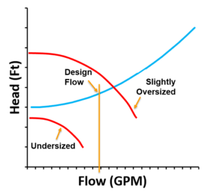
Figure H: Under-sizing pumps in open hydronic systems
Case Study 1 – Existing High-Rise Condominium Complex
A DHW recirculating system in a 16-story condominium complex was maintaining too high of pressures on the lower floors for the building. Investigation into the system revealed it was designed to have a PRV installed in the piping serving the DHW risers which fed Floors 1-8. The design matches the schematic shown in Figure G. However, the PRV was never installed during construction, thus the high pressure on the lower floors was realized.
The owner’s association brought in a contractor to install a PRV where the design called for it. Installing the PRV resulted in lower pressures on the lower levels, however, most condominiums almost immediately reported 5 minutes or longer delays before hot water was available at their showers.
Further investigation revealed that though the design called for a PRV, the recirculating pump installed to serve the lower floors could not produce enough head to overcome even the fixed pressure drop that resulted by introduction of the PRV.
There were essentially three options for supplying the additional head into the system to generate the required flow.
- Option 1: Upsize the lower floor’s recirculating pump. This pump was located on the top floor. Analysis of this hydronic system showed the suction side of the pump would be operating at negative gauge pressure. Negative gauge pressures can allow for air to leak into the system. It can also increase the risk of cavitation in the pump; however, this is typically not of concern due to the lower temperatures DHW systems operate at, which correspond to quite low vapor pressures.
- Option 2: Upsize the lower floor’s recirculating pump and move the pump to a lower floor. This would absolve the negative gauge pressure concerns.
- Option 3: Keep the current pump and install an additional pump in series at a lower floor. Though installing pumps in series is not typically advised, this is the option eventually chosen as it was the cheapest option for the owner’s association.
Case Study 2 – New High-Rise Office Building
A DHW recirculating system in the design of a new high-rise office building called for single recirculating pump to serve both the lower floors downstream of a PRV as well as the upper floors not requiring a PRV (see Figure I below). Check valves were installed on each of the lower floors where the DHW enters the return riser. The pressures shown in Figure I correspond to a scenario with zero flow in the system, which makes it easier to comprehend that flow will never move through the lower floors’ check valves. Though the pressures on the left side of the check valve will decrease when the pump is running, they will remain greater than the pressure on the right side of the check valve in all operating scenarios. Since water flows from high pressure to low pressure, flow will never be recirculated from the lower floors. Not only will this result in no hot water on-demand for the lower floors, it also creates large sections of pipe with stagnant water, posing health concerns.
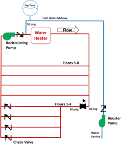
Figure I: Case study 2’s initial design
This design error of serving different pressure systems (Floors 1-4 with a PRV, and Floors 5-8 without one) with the same pump was identified prior to installation. The final design more closely aligned with the schematic as shown in Figure G.
Conclusion
Inclusion of PRVs in high-rise DHW recirculation systems is often necessary to maintain appropriate static pressure requirements at served fixtures. However, there are implications associated with doing so which need to be accounted for. Specifically, inclusion of a PRV essentially creates a system which exhibits all the characteristics of an open hydronic system. This is not intuitive, as many engineers associate open hydronic systems with those which have an elevation change associated with them. Pumps serving a system which includes a PRV need to first overcome the fixed pressure drop associated with the presence of the PRV before they can push any water. If the PRV is not appropriately accounted for, under sizing of the pump is very likely, which will result in no recirculated flow, and hot water will not be on-demand at most fixtures.
References
- International Association of Plumbing and Mechanical Officials. 2012. 2012 Uniform Plumbing Code.
- International Code Council, Inc. 2017. 2018 International Plumbing Code.
- Steele, Alfred. 2003. “High-Rise Domestic Water Systems.” Plumbing Systems & Design.
- Ayala, G. Zobrist, D. 2016. “Testing For and Determining the Prevalence of Crossover in a Multifamily Central Domestic Hot Water Distribution System.” ACEEE Summer Study on Energy Efficiency in Buildings.
- 2016. ASHRAE Handbook – HVAC Systems and Equipment.