
Unstable Transitions in HVAC Operations: Chiller Rotation Part I
Miles Ryan, P.E., writes a monthly column in Engineered Systems Magazine on Building Commissioning. Read November’s column below:
Periods of instability in HVAC systems often occur during necessary transitions in system operation. Examples of such instances include when a system first enables, goes from an occupied to an unoccupied mode of operation, or key components of the system (chillers, pumps, etc.) stage on or off to meet system demands.
Additional provisions in the automation of these systems are required to minimize the effects of these disturbances. Typically, not all the kinks are worked out prior to the functional performance testing directed by the commissioning provider. Our testing processes should be paying extra close attention during the transitional periods to identify any levels of unexpected instability, and we should also have a solid understanding of the tools available to the temperature controls contractor to improve performance in such instances.
Last month’s column detailed an example of how additional provisions in the BAS programming were needed to allow for the stable transition of an operating room from an occupied mode of operation into an unoccupied mode of operation. This month’s column examines provisions needed to prevent tripping chillers offline when rotating between chillers during periods of low system flow.
Chiller Rotation: Preventing evaporator flow switch trips
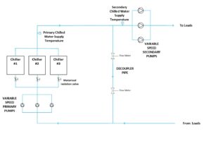
Figure 1: Chilled water plant diagram for a variable primary / variable secondary system.
Figure 1 shows a schematic of a central chilled water plant I recently worked on. It was a variable speed primary / variable speed secondary system configuration. Cooling demand from served loads (AHUs, CRAC units, FCUs and process cooling applications) dictated the secondary flow. Flow meters in the decoupler pipe were used to control the primary pumps. Those primary pumps were staged and their speed modulated to maintain a positive 100 GPM of flow from the supply piping to the return piping, as measured by redundant flow meters in the decoupler pipe. Keeping flow in this direction ensures the appropriate secondary chilled water supply water temperature was consistently sent out to the served loads.
Some of the served loads (FCUs, CRAC units and process cooling applications) needed year-round cooling. During colder ambient temperatures, the secondary flow drops significantly as there was no demand from AHUs. The primary flow rates naturally track downwards as well. There was a provision in the logic to prevent primary flow from ever dropping below a value that would not satisfy the active chillers’ minimum evaporator flow rate requirements. The chillers came with an integral flow switch which will disable the chiller if measured flow does not exceed the minimum evaporator flow rate, which was 530 GPM per the approved chiller submittal. The BAS works to keep the flow rate from not dropping below 600 GPM (for one active chiller) or 1,200 GPM (for two active chillers), as to prevent the chance of tripping such a flow switch. This additional control provision would essentially override primary pump speed command at times, which would result in more than 100 GPM of flow going through the decoupler. When this minimum flow control loop takes precedence, we say the plant is operating in a minimum flow scenario.
The plant will find itself in a minimum flow scenario for long periods during the winter. A single chiller can handle the load, but to even wear and tear on the chillers, lead chiller rotation still needs to occur. It was the rotation of the lead chiller, while the plant was in a minimum flow scenario, that created instability in the system.
Here is how it would go down. The secondary flow rate (dictated by cooling demands at served loads) hovered around 350 GPM. The primary pump would be in a minimum flow scenario, with the control loop working to keep a minimum flow of 600 GPM taking precedence for primary pump control. The time would come for the operating chiller to rotate. The design intent was to bring on the incoming lead chiller, run it in parallel with the outgoing lead chiller for several minutes, and then disable the outgoing chiller. The initial programming raised the minimum flow setpoint from 600 GPM (1 active chiller) to 1,200 GPM (2 active chillers) at the same time the incoming chiller’s isolation valve was commanded open. The incoming lead chiller’s isolation valve opened relatively quickly, while the primary pump(s) ramped up at a slower rate. This resulted in the primary flow being split between the now two available paths of flow, but there was not enough primary flow to satisfy either of chiller’s flow switches. This resulted in the outgoing lead chiller (the one that was already running) to trip offline on a loss of flow detected by its integral flow switch soon after the incoming lead chiller’s isolation valve was commanded open. The owner and design engineer were not okay with tripping a chiller offline in lieu of disabling it and letting the chiller go through its internally programmed wind-down process. Additionally, there was a spike in chilled water supply temperature when this occurred since the incoming lead chiller would take a bit before it was adequately cooling down the portion of water being sent through its evaporator. The facility operations team also did not like the alarm notifications that resulted from this event.
The Fix: Attempt 1
To prevent tripping the outgoing lead chiller as soon as we opened the incoming lead chiller’s isolation valve, the temperature controls contractor put in a provision that the minimum flow setpoint would be raised from 600 GPM (1 chiller) to 1,200 GPM (2 chillers) 4 minutes prior to opening the incoming lead chiller’s isolation valve. This would ensure there was enough flow in the primary loop to simultaneously satisfy both chillers’ flow switches when that incoming lead chiller’s isolation valve begins to open. Essentially, we give the minimum flow control loop a head start on achieving the elevated setpoint of 1,200 GPM prior to initiating the chiller rotation.
This fix worked…kind of. We tested the logic adjustment by again forcing a chiller rotation while the plant was in a minimum flow scenario. The primary flow got up to 1,200 GPM prior to opening the incoming lead chiller’s isolation valve. The outgoing chiller stayed running stably and the incoming chiller enabled as expected during the overlap period. The outgoing lead chiller was eventually disabled and after a little delay, its isolation valve was commanded closed. The moment that valve was commanded closed however, primary loop flow drastically dropped, and the incoming lead chiller tripped out on loss of evaporator flow.
We realized there was another point of concern during the rotation process that we never got to witness previously. The programming was dropping the minimum flow setpoint from 1,200 GPM (2 chillers) to 600 GPM (1 chiller) the moment the outgoing lead chiller’s isolative valve was commanded closed. The primary pump(s) ramped down to obtain the new setpoint, but the issue was the isolation valve takes time to close. Flow was still being split between the two paths of flow (i.e. the two chillers). Flow through the incoming lead chiller dropped below 530 GPM and the integral flow switch tripped the chiller offline. Our first attempt to prevent instability during chiller rotation prevented the instability when we entered the overlap period, but we were realizing there was instability that occurred when we exited of the overlap period that also needed to be addressed.
The Fix: Attempt 2
The next adjustment was a bit obvious, and it is very similar to the approach put in place in the operating room example detailed in last month’s column. When the plant was coming out of the chiller overlap period, the minimum flow setpoint would be slowly walked down from 1,200 GPM to 600 GPM over a several minute period. We also would not start walking that setpoint down until that outgoing lead chiller’s isolation valve was proven closed by use of the valve’s position feedback. Figure 2 details the order of events. This adjustment was performed, tested and proved to be stable; no flow trips on either of the chillers, minimum disruption in chilled water supply temperature (there is a slight rise while we wait for the incoming chiller to ramp up), and no alarms!
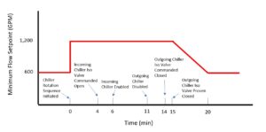
Figure 2: Chiller rotation sequencing required to prevent flow switch trips.
Conclusion
Commissioning providers need to pay extra attention to major operational transitions when testing HVAC systems. That is where instability often occurs. Post additional members of the team either on different computers to review multiple items on the BAS simultaneously, or physically locate additional personnel throughout the building when necessary, as to allow for all areas of concern to be reviewed simultaneously. It is relatively easy to get a system to run well in one mode or another, it is much more difficult getting it to go through major transitions smoothly. Next month’s column will continue to look at this chiller rotation scenario, but the focus will turn to instability witnessed on the condenser water side.