
Improving HVAC Operations – Part IV: Comprehensive Sensor Management
Abstract:
Maintaining a solid understanding of how common HVAC systems are controlled is essential to effectively troubleshooting them. It is also necessary for optimizing the energy performance of such systems. Improving the knowledge base of HVAC control sequences throughout the Department of Defense, for these purposes, was the driving force behind the resurrection of the Air Force Institute of Technology’s course entitled WENG 563 HVAC Control Systems. This 5-part series is written to support that course. These articles seek to explain common HVAC control sequences, where such sequences are effective, and the performance implications that arise when they are applied inappropriately.
Please enjoy Part IV of this series below written by Questions & Solutions Engineering’s own Miles Ryan, PE, CEM.
Part IV: Comprehensive Sensor Management
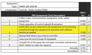
There is an extraordinary amount of sensors located throughout our heating, ventilation and air conditioning (HVAC) systems. Properly functioning sensors will ensure our systems will effectively meet their intended purpose in a more energy efficient manner. It should be no surprise that sensor calibration is included in the Air Force’s Preventative Maintenance Task Listing (PMTL). Table 1 shows the PMTL’s requirements for sensor calibration on water-cooled chillers. Similar verbiage is used for other HVAC equipment and subsystems. This verbiage provides some latitude. It is understandable that stricter language to force calibration on all sensors at prescribed intervals is not feasible. However, the PMTL verbiage may be interpreted to allow for shops to omit sensor calibration altogether. This would be entirely unacceptable, yet numerous conversations during courses I deliver reveal many bases only calibrate or replace sensors when ineffective system operation highlights their inaccuracy. The issue is many HVAC systems can deliver their intended purpose (e.g. occupant comfort) with uncalibrated sensors, they just do so in a very energy inefficient manner. The purpose of this article is to assist bases in understanding which sensors are to be prioritized for reoccurring calibration, as well as to understand other pitfalls which reduce sensors’ effectiveness.
Table 1: PMTL for Water Cooled Chiller Controls.
Prioritizing Sensors
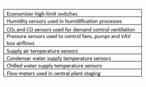
As previously stated, inaccurate sensors lead to inefficient operation, yet the systems they serve may continue to meet their intended purpose. Since sensor inaccuracy may not be easily identified by building occupants or facility managers, we need to prioritize certain sensors for reoccurring calibration based on the risk they pose to system efficiency when their accuracy drifts. In a 2010 article, Mark Hydeman introduces the term money sensor to describe such sensors. Coming from a consultant’s perspective, he defines the money sensor as “a sensor on which a small error in accuracy can yield large changes in your client’s utility bill.” They are the sensors used in the critical control sequences of an HVAC system. As there are many different sequences employed in our numerous HVAC systems, speak with your Energy Management and Control System (EMCS) technicians to help identify such sensors. A list of some of the money sensors Hydeman identifies can be seen in Table 2.
Table 2: Partial list of the money sensors (Hydeman, 2010).
Specifying the Correct Sensors
It should be noted that not all sensors identified by Hydeman can be easily calibrated. For example, a flow meter on a chilled water plant used for staging chillers is virtually impossible to calibrate in the field (Energy Design Resources, 2009). Therefore, it is vital the base’s mechanical engineers ensure higher quality sensors for such applications are specified for new installations. Comprehensive sensor management is not solely the responsibility of the HVAC and EMCS technicians.
Correct Mapping of Sensors
In that same 2010 article, Hydeman describes a time when he was calibrating sensors in a 17,000-ton chilled water plant. During the process he realized the condenser water supply and return temperature sensors were swapped in the control logic. This effectively meant the cooling tower fans – controlled to maintain condenser water supply temperature at setpoint – were running at far higher speeds than need be as they were inadvertently reading the much warmer condenser water return temperature. Hydeman’s work to improve the plant’s control sequences, saved on the order of 2.5 gigawatt hours annually. Diving into our systems through re- or retro-commissioning and reoccurring prioritized sensor calibrations can help identify such costly mistakes.
Sensor Location Concerns
Sensor location and installation is also critical to their performance. One example is the placement of an outdoor air temperature sensor. This should be located away from an exhaust air stream which will affect its reading. Additionally, it may need a radiation shield to prevent direct sun exposure from inducing higher-than-actual readings, which may prematurely halt an air side economizer (Ryan and Dill, 2019). Another example would be the location of the ports of a differential pressure sensor used to control relief fans to maintain positive building pressure. If the outdoor port is subjected to wind gusts, or the indoor port is near an exterior door, elevator shaft or behind drywall – placed by an unsuspecting carpenter during a renovation – issues will ensue. The readings may be off or fluctuate in a manner which creates instability not only in a relief fan’s operation, but throughout the rest of the system as well (Sellers 2003, Taylor, 2000). The base mechanical engineer needs to be on the lookout for problems during both the design and construction phase. Additionally, they need to ensure critical sensor locations, such as a supply duct static pressure sensor which is typically located above a ceiling outside of a mechanical room, are added to the construction drawings. This is often not the case, which can lead to a lifetime of neglected sensor calibration (Moser, 2015).
A Partial Solution with Dual Benefits
The criticality of some sensors can be alleviated when they are used with demand-based reset. The most common demand-based reset strategies adjust the pressures and temperatures an HVAC system operates at to improve its effectiveness and efficiency (Seidl, 2008). One example would be the simple supply air temperature setpoint reset sequence described in a previous article (Ryan, 2019). Another would be a static pressure setpoint reset sequence described here.
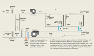
Figure 1: A VAV system implementing a static pressure reset sequence will find the most appropriate setpoint to optimize fan energy performance despite slight inaccuracies in the supply duct static pressure sensor.
Figure 1 shows a common cooling-only variable-air-volume (VAV) system. The damper in each zone’s VAV box modulates the amount of cool air that is sent to the space based off the space’s cooling requirements. As cooling requirements decrease, the various VAV dampers will start to close, and the static pressure in the supply duct will increase. A supply fan equipped with a variable speed drive will slow down the fan to bring the static pressure back to setpoint.
Slowing down the fan speed saves a lot of fan energy, but even more can be saved. Imagine all the zones served by the ducted system have minimal cooling requirements and all their dampers are substantially less than fully open. The supply fan would be operating at a reduced speed, but the less-than-fully open dampers create a restrictive path to push air through. Thus, the fan must work harder than need be by injecting additional pressure into the system, only to have it bled off as the air passes the partially closed dampers.
If the static pressure setpoint was continuously reset to ensure at least one damper is near fully open (e.g. ~90%), the fan would have to push air through a less restrictive path and thus save even more energy. Such a reset sequence finds the static pressure setpoint that is best for the system’s operating state despite slight inaccuracies in the pressure sensor. Implementing such a sequence can reduce fan energy consumption by up to 50% when compared to maintaining a fixed setpoint (Hydeman and Stein, 2003). Yet Kevin Moxley from the Civil Engineer Maintenance, Inspection and Repair Team at Tyndall AFB, who has been troubleshooting Air Force facilities for over 35 years, estimates only 20% of multi-zone VAV systems in the Air Force employ them. What an opportunity for us to both save energy and mitigate the consequences of our failure to calibrate these sensors!
Conclusion
Controlling our HVAC systems correctly can result in substantial energy savings. Accurate sensors help ensure these savings are realized, but calibration alone will not suffice. Comprehensive sensor management requires many throughout the base to appreciate the importance of sensor accuracy in our HVAC systems and be able to identify and mitigate the pitfalls that can affect sensor performance. The intent of this article is to start the discussion on what a comprehensive senior management plan could look like for your base.
References:
- Energy Design Resources. (2009). CoolTools™ Chilled Water Plant Design Guide.
- Hydeman, M. (2010, April). Take Care of the Money Sensors. Consulting-Specifying Engineer.
- Hydeman, M., & Stein, J. (2003, May). A Fresh Look at Fans. HPAC Engineering.
- Moser, D. (2016). Show Me the Sensors. ASHRAE Journal, 58(9).
- Ryan, M. (2020). Improving HVAC Operations Part II: Controlling Temperature, Managing Humidity.
- Ryan, M., & Dill, J. (2021). Improving HVAC Operations Part I: Managing Swing Season Cooling Requirements.
- Seidl, R. (2008). Using Demand Based Reset Strategies. National Conference on Building Commissioning.
- Sellers, D. (2003, July). 21st-Century HVAC Controls: Progress and Paradox. HPAC Engineering.
- Taylor, S. (2000). Comparing Economizer Relief Systems. ASHRAE Journal, 42(9).
Ryan is a commissioning engineer at Questions & Solutions Engineering in Chaska, MN. As an Air Force Reservist, he serves as a mechanical systems instructor at the Air Force Institute of Technology (AFIT). He is one of the developers of the HVAC Control Systems course taught at AFIT.